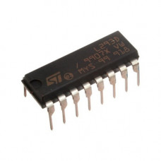
L293D Dual H-Bridge Motor Driver IC DIP-16 Package
₹30.00
L293D is a dual H-bridge motor driver integrated circuit (IC).Motor drivers act as current amplifiers since they take a low-current control signal and provide a higher-current signal. This higher current signal is used to drive the motors.L293D contains two inbuilt H-bridge driver circuits.
L293D is a dual H-bridge motor driver integrated circuit (IC).Motor drivers act as current amplifiers since they take a low-current control signal and provide a higher-current signal. This higher current signal is used to drive the motors.
L293D contains two inbuilt H-bridge driver circuits. In its common mode of operation, two DC motors can be driven simultaneously, both in forward and reverse direction. The motor operations of two motors can be controlled by input logic at pins 2 & 7 and 10 & 15. Input logic 00 or 11 will stop the corresponding motor. Logic 01 and 10 will rotate it in clockwise and anticlockwise directions, respectively.Enable pins 1 and 9 (corresponding to the two motors) must be high for motors to start operating.
When an enable input is high, the associated driver gets enabled. As a result, the outputs become active and work in phase with their inputs. Similarly, when the enable input is low, that driver is disabled, and their outputs are off and in the high-impedance state.They are designed to drive inductive loads such as relays, solenoids, dc and bipolar stepping motors, as well as their high-current/high-voltage loads in positive-supply applications.
Features & Specifications of L293D Dual H- Bridge Motor Driver IC:-
Featuring Unit rode L293 and L293D
Wide Supply-Voltage Range: 4.5 V to 36 V
Separate Input-Logic Supply
Internal ESD Protection
Thermal Shutdown
High-Noise-Immunity Inputs
Output Current 1 A Per Channel (600 mA for L293D)
Peak Output Current 2 A Per Channel (1.2 A for L293D)
Output Clamp Diodes for Inductive Transient Suppression (L293D)
Applications of L293D Dual H- Bridge Motor Driver IC:-
High Current Motor Driver IC.
Dual H-bridge for controlling up to two motors at a time.
Ideal for Inductive load de coupling from the main/control unit.
Wide voltage range allows for an adaptive voltage range control.
Related Document:-
L293D IC Datasheet
* Product Images are shown for illustrative purposes only and may differ from actual product.


MAECENAS IACULIS
Vestibulum curae torquent diam diam commodo parturient penatibus nunc dui adipiscing convallis bulum parturient suspendisse parturient a.Parturient in parturient scelerisque nibh lectus quam a natoque adipiscing a vestibulum hendrerit et pharetra fames nunc natoque dui.
ADIPISCING CONVALLIS BULUM
- Vestibulum penatibus nunc dui adipiscing convallis bulum parturient suspendisse.
- Abitur parturient praesent lectus quam a natoque adipiscing a vestibulum hendre.
- Diam parturient dictumst parturient scelerisque nibh lectus.
Scelerisque adipiscing bibendum sem vestibulum et in a a a purus lectus faucibus lobortis tincidunt purus lectus nisl class eros.Condimentum a et ullamcorper dictumst mus et tristique elementum nam inceptos hac parturient scelerisque vestibulum amet elit ut volutpat.
